Pages maintained by Rattlebars
Mfg. Support our affiliates! Click above!
| The information on these pages is
accurate to the best of the author's knowledge. The
author can assume no responsibility for the use or misuse
of this information by the reader. The reader is expected
to secure any other information needed from Service
Manuals or other sources. It is up to the reader to
determine his/her ability to make any modifications
noted. If the reader does not feel qualified he/she
should enlist professional help. |
RETURN
TO THE GOODIES INDEX
Debulking the
Valkyrie
AN
OXYMORON MADE REAL
NightMare
is leaner and meaner than ever!
By Chet Walters
Click any picture to see
enlargement
Click resulting picture to see next
Use backspace key for previous |
|
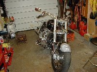 |
UH! OH! What's happening here? Well, to start...
disassemble .\ Front end to get chromed by H&R Plating. They can do yours
too!
|
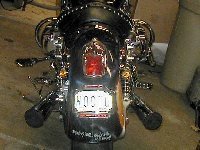 |
Phase one - the rear end. This is a the sum total of
all the lights that will be on the rear of the bike.
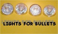
SMALL Kuryakyn Small Universal mount Silver
Bullets (2305) are mounted "visor in" under
the fender rails. They look like little rocket engines
back there. Very clean and non bulky (shown here with
amber lenses and these come with interchangeable lenses -
clear, red, amber). Halogen bulbs from the track lighting
section of Home Depot can be used (only $7.50 per -- see
below) and come in various wattages (20 - 35 - 50). For
these SMALL bullets, can't use 50 and the 35 watters are
too bright too so these are equipped with 20 watters.
Holes were drilled in the fender rails for mounting with
supplied 3/8" bolt. The bolt was cut to length and
the edges smoothed so it would not hurt the wires. Added
a little shrink wrap where the wire strikes the bolt for
extra protection. Just screw the bolt in and figure how
long to cut it for your application. (NOTE: Kury silver bullets (2303) now come with a no visor bezel and you can get a visor in whatever orientation that suits your application) |
 |
Current plate frame was merely bolted to the fender
over the existing signal cluster rubber grommet left in
place. Holes were drilled through the Ness Tech 12-102 flat backing plate and
carriage bolts run through the backing plate into the
orignal holes in the fender with nuts applied right where
they used to be for the entire signal/license assembly
which was discarded. The lighted plate frame is (#9167) Kuryakyn
for only $35. Signal Dynamics LED is hung offa piece
of stainless which is double stick taped to the back of
the plate and the LED is double sticked to the stainless.
Triple LED's (#CYC-032) on each side are
double stuck to the plate back and are hooked up to glow
all the time but the ground wire is run to the HOT wire
of each signal so that they blink inversely with the
signals (when the signal goes hot, the LED loses
"ground" and goes off). |
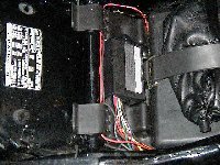 |
The wiring is accomplished using a Badlands
Illuminator module which makes the bullets act as
running lights, brake lights and turn signals. Very
bright. The Badlands module is placed upside down under
the seat nestled between the tool box/battery box mounts
in the rear. This yields a compact installation and easy
access to the necessary connections under the right side
cover for the rear fender harness. Click here to go to the wiring
diagram.
|
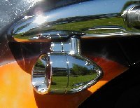 |
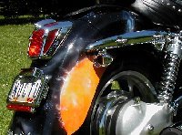
Closeup picture of the small bullet mounted on the
fender rail. A ½" hole was drilled in the rail at
an angle and the Bullet mounting bolt was shortened. The
edges were coated with Plasti-Kote® Clear Touch Up paint
#3001 and a 1/4"ID x 1/8" O-ring was used to
cover the gap produced by the flat surface of the Bullet
and the curved surface of the fender rail. A simple lock
washer on the inside served to correct the flat bolt head
mating with the curved inner fender rail. |
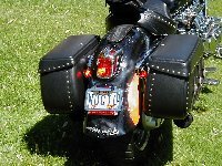 |
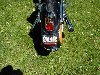
Shown here with LeatherLyke bags and also the light
blinking. Very interesting and very bright. These lights
tuck in very nicely in the gap between the fender and the
LeatherLyke bags and are surprisingly visible up to about
20° laterally. These small bullets will also fit in the
gap between the fender and the stock Honda hard bags but
I have not experimented with visibility on that kind of
installation for obvious reasons. YMMV |
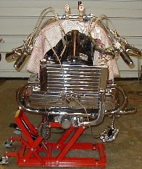 |
Debulking! OOOPS! Have I gone too far????!!! Front
end gets chromed by H&R Plating. They can do yours
too!
|
 |
Since the elimination of the Cobra Light Bar meant
the loss of the turn signals and marring the newly
chromed fork tubes with stock signal mounts was out of
the question, Kury silver bullets mounted to the radiator
sides was to be the new front turn signal solution. They
are mounted where the molding "hole" is under
the reflector which puts them at the narrow part of the
radiator underneath the side covers making room for the
bolt heads and wiring. |
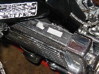 |
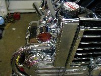
Thankfully, Kury supplies good long heat resistant
silicon coated wiring with the Silver Bullets. Here, the
wires are run along the top of the radiator, under the
frame then into the main harness into the headlight. The
runs along the radiator tops are covered afterwards with
a Rattlebars Rad Top Kit
making for a very neat look. Grounding the lights was
done with little pigtails that merely hook to the
radiator side cover bolts. The side cover bolt holes are
covered with ¾" allen screw caps. |
 |
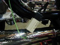
These function well with both the big windshield and
mini light bar lamp configurations detailed below. They
are wired with Tail/Turn
Converters from Lazer Star (mounted in the nacelle as
shown) so the single filament bulbs can act as both
running lights and turn signals. They are fairly bright,
but the modules seem not to function as well as the
Badlands item for the rear. The lights are a little
dimmer than they should be and you can only run 20Watt
lamps in them. I have built an alternative module for my
VTX which uses relays and costs only about $10. See the
note at the end of this page for more information. |
 |
Unfortunately, the use of these front modules and the
Badlands rear module causes the stock turn signal flasher
to go into "bulb out" mode and the signals
flash at double rate. One solution was to add a 35 Watt
stock bulb to each circuit, but that would leave one
figuring out how not to show the light from this also
fragile bulb. Final solution was to put a pair of 10 Ohm
10 Watt wire wound resistors to ground on each of the
signal circuits to put enough load on the line so that
"bulb out" was not a problem. See note at the
end of this page for more information. |
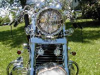 |
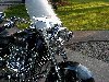
A "mini" light bar was made with the stock
Hondaline lower WS bracket and a couple of Kuryakyn SMALL
Silver Bullets with 35 Watt spots. This pic also gives a
good view of the chromed TBR triple clamp and the fork
tubes. Note here how the stock mirrors are merely flipped
over 180° to reduce the "dumbo ears" look that
plagues the Valkyrie "beach" handlbars with
stock mirrors. I have not found any custom mirrors that
match the excellent view that the stock mirrors provide
and this orientation actually improves the view and the
look! |
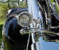 |
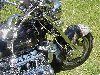
The mini light bar bullets were mounted with
fabricated brackets to the stock lower WS bracket bar and
remove easily for installation of the big Hondaline Sail
for cold weather riding (see below). They are "self
adjusting" and when mounted, are automatically
aligned. The wires simply unplug and the lamps require
only a 10mm wrench to remove. |
 |
The mini light bar bullets lamps can be obtained from
many sources for about $6 - $7.00. Home Depot, Lowe's,
Christmas Stores (year round ones), some hardware stores
and any lighting shop that carries track lighting. Just
look for 12v lights in the proper wattages. I perfer
spots since floods often don't put out much light up
front, but they do light up the road nearby. |
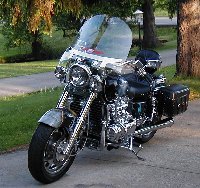 |
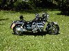
Here she is in "touring/cold weather" mode.
The Hondaline has mounted with simple right angle
brackets on the lower windshield bolts, 4½" lamps
which replace the Mini Light Bar rather nicely for a more
"bulked up" look that goes with the big shield.
These lamps simply plug in where the mini light bar
bullets once did. Switching for both the light bar and
these lamps is accomplished using the kill switch as
detailed on my Kill Switch
Page. |
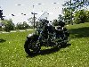
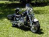
| BELOW CAN BE SEEN SEVERAL OTHER
VIEWS OF THE DE-BULK |
 |
 |
 |
 |
 |
 |
|
BADLANDS MODULE WIRING FOR HONDA:
The wiring for the Badlands module can be seen
seen at left. There are two options and you MUST only use
one of them. One option to make the Badlands module work
with fourways when the
key is off is to hook up the BADLANDS
ORANGE to a +12v fused
lead off the battery (as they instruct). This way, the
module is always ready to light your signal lights
whether the key is off or on.DON'T
DO BOTH OPTIONS!
Or, you can simply tie the BADLANDS
ORANGE to the taillight lead just like
you do the BADLANDS GREEN
which will have the unit switched off with the key (but
your fourways will
only work when the key is on).
DON'T DO BOTH OPTIONS!
At this writing the
Badlands module colors matched this drawing. Please note
that the taillight wires on Honda's have different traces
(or no traces) but BROWN is always involved (VTXc
BLACK/BROWN - VALK ST/TOUR LIGHT BROWN or BROWN/WHITE-
VALK I/S BROWN/WHITE).
|
| NOTE: I also put Silver Bullets on my VTX and
I built my own front signals/fog/running light module
using relays for the front turn signals on that bike
(this will also work well for the Valkyrie). The relays
are five prong with normally open (87) & normally
closed (87a) output terminals. However, here the output
terminals are used as input terminals while the input
terminal (30) is used as the output terminal to the
lamps. The trigger terminal (86) on each relay is hooked
up to the front running light wires. The principle is
that the running light wires go hot when the bike key is
turned on and this triggers the relays. Current is fed to
the lamps directly from the battery through the normally
off terminal (87) hence the lamps are always on to serve
as 35 watt fog lamps/running lights. These are very
bright and not only make you more visible to other
drivers, they help light up the road at night. |
|
On Hondas, when you put on your turn
signal, the running light on that side is switched off. Put on a
blinker and the running light wire goes cold so the relay for
that side gets "untriggered" and reverts to
"off" hence cuts the steady running light current from
the battery through terminal 87 and then feeds current to the
lamp from the intermittent turn signal circuit through the
normally on terminal (87a) of the relay. You have a blinker! Very
bright. Very noticeable. This circuit costs only about $10 to
build and will work if you just leave the rear signals as stock
too. This also eliminates the "bulb out" problem
discussed above so the extra wirewound 10ohm resistors are not
necessary.
But, the "running light out when signal on" feature
of Honda's signals allows you to also wire them up more simply as
shown at the left usind diodes (diodes pass current only one way,
the banded side won't let any current through). I have had
diode's burn up and cause me grief. But I was using lighter
diodes (RS 276-1114). At the suggestion of HonDiego of the VTXOA,
I have installed more stout Radio Shack epoxy rectifiers (RS
276-1144) which seem to work well. They get hot so keep them away
from vital organs. I have not tested these yet on a full day's
ride but I suspect they will work ok. Problem is, there's no way
really to switch these off if you need to get some jiuce to start
your bike because the Kury silver bullets do not have isolated
ground. To wire the bullets with isolated ground, you need to run
an extra wire inside the light and pic up the ground there,
isolating it, and bringing it out to the switch.
However, there was one problem with the
Badlands module used for the rear signals in conjunction with
this setup. When the turn signal circuit was hot on one side,
there was feedback between the circuits through the blinker
indicator and both the rear lights blinked weakly as if there
were "fourways" on. Not good! As you can see by the
left side of the drawing, the blinker indicator on both the
Valkyrie Standard/Tourer models and also the VTX is fed by both
signal circuits. When the right signal circuit goes hot, the left
(cold) circuit acts as ground and blinks the indicator lamp. When
the left signal goes hot, the reverse is true. Unfortunately,
there was enough feedback current through the bulb on the VTX
that it confused the Badlands module. The solution was to
eliminate the feedback but preserve the blinker indicator. The
right part of the drawing shows how to do this using Radio Shack
diodes (diodes pass current only one way so there is no feedback)
and this has the bonus of making the blinker indicator brighter
since it removes the filaments of the blinker bulbs in the round
circuit. Ground LT BLUE to any GREEN wire or the frame and then
feed the ORANGE wire from both the LT BLUE and the ORANGE using
diodes.
For more information on relays and how they work, check Extra Horns How To
For more information on blinker indicators and how they work,
check Extra Blinker Indicators
NOTE ON BULB OUT: In wiring to disable
"bulb out" you must simulate the resistance of the OEM
35 watt signal filament. To do this, wire a pair of 10 Ohm 10
Watt wire wound resistors to ground on each of the signal
circuits to put a 5 ohm load on each line so that "bulb
out" will not be a problem. These are Radio Shack 271 - 132
and cost only 99¢ for a pair. Good cheap two dollar solution.
These do get warm so don't put them anywhere near plastic or
other wiring. I hung mine down by the swingarm behind the frame.
One could just wire a pair of these between the signal circuits,
but you risk the problem of "feedback" as discussed in
the above paragraph. Note, the actual resistors don't look like
the ones in the drawing. They are square
ceramic hickeys (that's the teck term for them) about two
inches long.
One final note: You can wire your single filament bulb for
signals and running lights like this keeping the ground isolated.
This is a quikie and note that if you have STOCK
SIGNALS IN THE BACK AND DO IT THIS WAY, YOU WILL MELT YOUR REAR
SIGNALS. If you have Kury Bullets back there,
you're just fine except they will be very bright. Might wanna use
20 watt bulbs from the hardware store track lighting section.

Thanks go out to Tim Skelton who provided the first
instructions on mounting a license plate this way. Also to be
credited are DragBars Christian for letting me get a good close
look at Kury Silver Bullets in Daytona and the San Diego crew for
a good look at clean rear ends.
RETURN
TO THE GOODIES INDEX
Questions? Contact Chet at  Chetspages@rattlebars.com