4 - 1K 2.5A diodes (Radio Shack 276-1114)
weather resistant electrical tape
Heat shrink tubing
Soldering iron
Solder

| The information on these pages is accurate to the best of the author's knowledge. The author can assume no responsibility for the use or misuse of this information by the reader. The reader is expected to secure any other information needed from Service Manuals or other sources. It is up to the reader to determine his/her ability to make any modifications noted. If the reader does not feel qualified he/she should enlist professional help. |
This mod works on four premises. 1) The fact that on Hondas, when you switch on a turn signal, the running light on that side gets switched off. 2) A "hot" wire will act as a ground wire when it's switched off. 3) Diodes conduct current (and ground) in one direction only. 4) You have a perfectly good but unused LED that requires ground to emit light.
ADDING INDICATORS
TIME: 60 minutes
|
MATERIALS 4 - 1K 2.5A diodes (Radio Shack 276-1114) weather resistant electrical tape Heat shrink tubing |
TOOLS Soldering iron Solder |
|
 QUICKLY FOR THE EXPERT: Isolating the front running light circuits with diodes, tie them onto the stand light so they act as ground when the signals are on and running lights off while at the same time feed current to them from the signal circuits so the ground will be intermittent causing the stand indicator LED to blink inversely with the blinkers.
QUICKLY FOR THE MOTORHEADS: See the drawing. We use diodes to allow the running light wires to act as ground for the stand light when the running lights get switched off as the turn signals get switched on. Because we'd like the new turn signal indicator light to blink instead of emit steadily, we use diodes to feed the intermittent blinker current to the running light circuit so that it will interrupt the switched off ground properties inversely as the blinker blinks. Since these circuits must be kept isolated, two diodes are used to tie in the single ground for the new indicator and two diodes separately tie in the left/right blinker circuits.
NOTE: this is a "layman's" drawing which shows only the various parts and connections. It is intentional that there are no electronic symbols used.
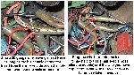
FOR THE REST OF US: Prepare for installation by pre-soldering your ground pigtail as shown in FIGURE ONE being very conscious of the way the gray band on the diodes is oriented (they should be AWAY from the single joint). Before you proceed, note that it is important to carefully tape up or heat shrink all the wires and diode leads so that there is no chance of a short circuit.
Disconnect the negative battery terminal as a precaution at this time. Remove your headlight rim by removing the phillips screws located at 4 o'clock and 8 o'clock on the rim. Placing your hand on the top of the rim to hold it in place, pull outward on the bottom of the rim to release. Holding the rim, unplug the headlamp and set the rim aside. Loosen the clips that hold the harnesses in place.
Pull the off-white connector so it is accessible (See FIGURE TWO) and locate the wire that is YELLOW w/ black trace (it's in a corner of the connector) which is the ground wire for the stand light. Strip a little so the wire is bare and solder the single lead of your pigtail. Tape it up good. Attach the other two ends of the pigtail, one each, to the running light wires (Left is ORANGE w/ white trace and right is BLUE w/ white trace). See FIGURE THREE for the easiest way to splice into a bullet connector without using solder. That's an easy way to do it and you can also easily remove it if you need to.
If you want your stand light to be a steady indicator, you can tape it up and button it up now, but if you want it to blink... Before you button that up with tape or plug it back in, jump your blinker wires so the new indicator will blink. With diodes, according to the drawing, jump the SOLID ORANGE to the ORANGE w/ white trace wire. Make sure that the diode is oriented with the gray band TOWARD the ORANGE w/ white trace wire. Do the same with the SOLID BLUE wire and the BLUE w/ white trace wire orienting the diode as above.
Tape it all up good (speaking of tape, check FIGURE FIVE for a hint on how to ease your use of electrical tape) and give it the smoke test. Sit on your bike and turn on the key. You'll see the stand light works as it always did (the stand switch merely grounds the LED). Raise the stand and the stand light goes out just as before (this light really defines the term idiot light does it not?) Put on a blinker. The stand light will now blink inversely with the blinker (making it a not so idiot light) because the running light circuits act as intermittent ground for the stand LED! As an added bonus, since both of your front light filaments are now blinking instead of just one, your front signals are a little brighter in contrast.
| CLICK IMAGE TO ENLARGE - CLICK ENLARGEMENT FOR NEXT | ||||
 |
 |
 |
 |
 |
| FIGURE ONE | FIGURE TWO | FIGURE THREE | FIGURE FOUR | FIGURE FIVE |
ALTERNATIVE EXTRA TURN SIGNAL INDICATOR
You can use any polarity unspecific 12 volt light to act as a turn signal indicator. Decide on a good place to mount the light and run one lead to the SOLID ORANGE left turn signal wire and run the other lead to the SOLID BLUE right turn signal wire. This works on the same principle that a "hot" wire acts as ground when it's not carrying current itself. When your left blinker is on, it feeds current the lamp and the right signal circuit acts as ground since it's cold. When the right blinker is on, the opposite is true. This is actually how your woefully inadequate stock blinker indicator light works, but you will choose a much brighter and better located light, right?? You can't use an LED here or some neon lamps because they are polarity specific. Radio Shack carries many types of 12 volt lamps for you to use in this application.
ALTERNATIVE USE FOR THE OLD TURN SIGNAL INDICATOR
If you have wired the stand light to act as your TS indicator, you can then use the old indicator for another purpose. You may want to use it to let you know that one of your added accessories is on and working. At the old indicator on the lamp side of the green six pin plug inside the headlight, cut the SOLID ORANGE and the SOLID BLUE between the green plug and the old TS indicator. Insulate separately the plug side wires then hook the SOLID BLUE TS indicator lead to your accessory's +12v supply lead (the one that's hot when the accessory is on which would normally be between the accessory and its switch). Where you hook up the SOLID ORANGE lead from the lamp will determine what it does for you. It can be lit to let you know your accessory is on and dark when it's off (like your hi beam indicator), or the opposite so it is lit when your accessory is off and dark when it is on (which could be a safety feature in that it will light up to let you know you've forgotten to turn on your light bar or some such).

To indicate an accessory is on: hook the SOLID ORANGE lead to ground. When your accessory is on, the lamp will be lit and when the accessory is off, the lamp will be dark.
To indicate an accessory is off: hook the SOLID ORANGE to any +12v source that is hot when the key is on (use a COFFEE WITH CREAM BROWN wire). This method works on the principle that a "hot" wire acts as ground when it's not carrying current itself. The "key on" +12v will do nothing to the lamp until the accessory is turned off at which time the lamp will be lit. But when the accessory is on, the lamp will be dark since no current flows (current flows like water from higher voltage to lower voltage). This may be a better solution in some cases since a constantly lit lamp may be distracting when used as an indicator for an accessory like a light bar that is mostly on instead of mostly off.
Thanks to Joe Engle for this unique idea on another use of the TS indicator.
 Chetspages@rattlebars.com
| More how-to articles for the Valkyrie | |||
|---|---|---|---|
| Feet Heaters | Extra Horns | Four Way Flashers | Carb shims |
| Signal Buzzer | Driving Lights | Horny Lights | Invisible Vista |
| Back to Chet's Valkyrie Page | |||